| Lead Loss Errors in Resistive Sensors |
|---|
| This technical brief discusses alternative circuit topologies used in resistance measurement systems and a characteristic common to all such circuits known as lead loss error. |
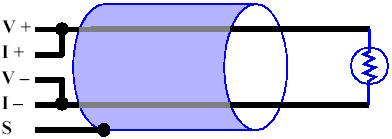
OverviewSeveral techniques are commonly used for measuring resistive sensors. Precision bridges are useful for measuring very large and small resistance values, as well as small changes in resistance. Extremely nonlinear sensors, such as thermistors, are often connected in series with a linearizing resistor — a resistance that tends to correct non-linearities over a narrow operating range. Such schemes require careful selection of the bridge completion or linearizing resistors based on the anticipated resistance range. Neither of these approaches is feasible in a versatile, multichannel sensor measurement system. Sensoray Smart A/D products (e.g., model 518) employ a method for resistance measurement that is universally applicable to a wide range of resistance values and sensor types. All supported resistive sensors, including RTDs and thermistors, are acquired by forcing a constant current through the target sensor and then measuring the resulting voltage. The sensor resistance is determined by simple application of Ohm's Law: RS=VS/I, where RS is the target sensor resistance, VS is the voltage across the sensor, and I is the excitation current. Four terminals are provided for each sensor: two for excitation (I+ andI-) and two for sensing voltage (V+ and V-). A constant excitation current flows from the I+ to I- terminal, and the voltage difference between the V+ and V- terminals is measured. As with any other resistance measurement technique, constant-current excitation has potential pitfalls. This article examines a side-effect of constant current excitation known as lead loss error, and how to avoid it. What is Lead Loss?All electrical conductors (except superconductors) have finite electrical resistance. The magnitude of a conductor's resistance is a function of its material, diameter and length. R = MaterialResistivity * Length / CrossSectionArea When current passes through a conductor, the electrical resistance of the conducting material will produce a voltage difference across the conductor according to Ohm's law. This resulting voltage is called lead loss. Note that lead loss increases with increasing conductor length. Lead Loss ErrorIf the distance from a sensor to its excitation source is small, a single conductor pair may be shared by both excitation source and measurement system without compromising measurement accuracy. As this distance — and consequently, conductor length — increases, measurement accuracy may be degraded due to voltage drops across the conductors. Such measurement error is classified as lead loss error. The diagram below illustrates lead loss in a two-wire circuit. In this case, the top conductor (T), which extends from the V+/I+ junction to the top of the sensor, has resistance RT and produces a voltage drop of magnitude VT=I*RT. Bottom conductor (B) produces a voltage drop equal to VT=I*RB. The sensor resistance, shown at the right, produces the voltage we are interested in measuring: VS=I*RS. Two-Wire Circuit
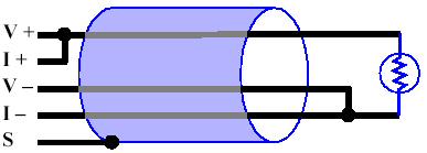
Lead loss error occurs when lead loss is sufficiently large to impact the accuracy of a resistance measurement. Such errors are a consequence of attempting to measure a target resistance located at the far end of a conductor, when in reality, it is thesum of the target resistance plus the conductor resistance that is being measured. Referring to the above example again, it can be seen that Rmeasured = (VS + VT + VB) / I = RS + RT + RB It can be seen that measured resistance increases as conductor lengths — and corresponding RT and RB values — increase, reducing the accuracy of the target resistance measurement. Such errors can become unacceptably large when measuring small resistances such as RTDs. Avoiding Lead Loss ErrorsTwo methods are available for limiting lead loss errors. In some cases, lead loss can be limited to an acceptable level by keeping conductor lengths sufficiently short or by using larger diameter conductors. If this is not practical, one or two extra conductors can be added to reduce or eliminate losses, resulting in what is commonly referred to as a three-wire or four-wire circuit. In such circuits, the objective is to separate excitation and voltage sensing functions onto different conductors. Three-Wire CircuitsA three-wire circuit, shown below, will reduce lead losses by 50 percent. Although the third wire is shown connected at the bottom of the target resistance, it could just as easily be connected at the top. The advantage provided by the third conductor is this: since no current flows through the conductor that connects V- to the sensor, it experiences no lead loss. The top conductor continues to produce lead loss error. Three-Wire Circuit
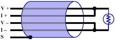
Four-Wire CircuitsA four-wire circuit is shown below. This circuit topology completely eliminates lead losses by having two sense leads and two excitation leads. Since no current flows through either of the sense leads, the measurement system is able to directly access the voltage at the target resistance. Four-Wire Circuit
In a four-wire circuit, it is a simple matter to compute the sensor resistance: RS=VS/I. Clearly, the four-wire circuit provides superior measurement accuracy regardless of conductor length or wire diameter. Because of the significant advantages offered by the four-wire circuit topology, all Sensoray Smart A/D products provide a complete four-wire circuit for each measurement channel. |