Multifunction analog/digital I/O | Model 425
- Three quadrature encoder channels with 24-bit counters
- Four 12-bit D/A outputs
- Eight 12-bit differential A/D inputs
- Watchdog timer
- 48 bidirectional digital signals
- Interrupts from counters and digital I/Os
Model 425 is obsolete. This archived information is provided as a courtesy to customers who own model 425 units.
Description
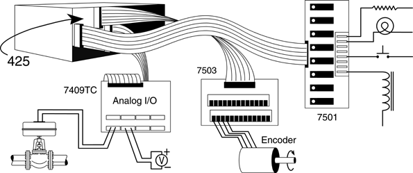
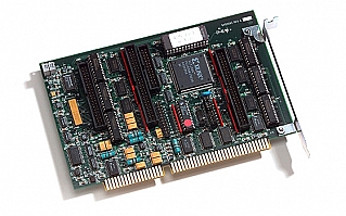
Sensoray's model 425 is a low-cost ISA bus interface that combines five popular functions on one board. It uses four low-profile headers and flat cables to connect its I/O interfaces to external breakout boards.
Typical Application

Encoder Interfaces
The board's 24-bit up/down counter channels are designed to work with incremental encoders or single-phase clock sources. Each channel accepts two TTL or RS-422 clock signals, plus an index signal, to track encoder direction and displacement. Unlike conventional counters, the board's counters do not accumulate errors when the encoder dithers or changes direction. The board supplies 5-volt operating power to all encoder channels through its connectors. Each counter can be programmed to function as an encoder interface or as a general-purpose timer and may optionally generate interrupts. To ensure maximum flexibility, no counter functions are shared by any other on-board peripheral devices.
A/D
Eight differential input channels are multiplexed to a sample/hold and high-speed A/D converter. A resistor-programmable instrumentation amplifier allows gains of 1 to 1000. An on-board DC/DC supply ensures A/D linearity for the full ±10 V input range.
D/A
The board has four analog output channels with a 0 to 10 V output range. One of the channels has remote sense inputs to compensate lead loss errors. All outputs are automatically reset to 0 V when a bus or soft reset occurs.
Watchdog
The board's watchdog timer output may be routed to either bus reset or nonmaskable interrupt. It may be enabled or disabled under program control. The timer is automatically disabled when a bus reset occurs.
Digital I/O
Model 425 has forty eight high-current digital I/O channels. The connector pinouts allow the channels to be directly connected to industry-standard solid relay boards. Each line is independently configurable as input, output, or wired-OR. Sixteen of the channels support edge detection with interrupts. When a system reset occurs, all output channels are automatically turned off.
Specifications
| Analog Inputs | |
|---|---|
| Conversion time | 20 µS |
| Number of channels | 8 differential |
| Input resistance | 100 MΩ |
| CMRR | 100 dB minimum |
| Maximum common mode voltage | 5 V |
| Resolution | 12 bits |
| Accuracy | 14 bits |
| Input ranges | ±10, ±5 V |
| Offset error | ±1/2 LSB |
| Analog Outputs | |
| Conversion time | 200 µs |
| Resolution | 12 bits |
| Offset error | ±2 LSB |
| Output voltage | ±10 V |
| Output resistance | 87 Ω |
| Digital I/O | |
| Number of channels | 48 bi-directional |
| Output voltage | 0 to 5 V, open collector |
| Output sink current | 100 mA (at 1.1 V) |
| Encoder Interfaces | |
| Number of channels | 3 quadrature, 16 bit |
| Input voltage | TTL or RS-422 |
| Input frequency | 350 kHz |
| Watchdog Timer | |
| Watchdog timer time-out | Time-out: 500 ms
2-pin connector may be connected to the bus reset line to allow a system reset from software |
| Power and Environmental | |
| Operating temperature | -25 to 70 °C |
| PC bus interface | I/O mapped, 16 ports |
| Input power | < 3 W |
Documentation
| File | Version | Date M-D-Y | Type | Size |
|---|---|---|---|---|
| Model 425 Instruction Manual | 1.0.0 | 10-17-24 | 351 KB |
Downloads
| File | Version | Date M-D-Y | Type | Size |
|---|---|---|---|---|
| Model 425 Software Development Kit | 1.0.0 | 10-17-24 | ZIP | 1.23 MB |
| Other Operating Systems | ||||
| Need a software development kit for another operating system? We can port our SDK to your OS for a NRE fee or, with a volume commitment, at no additional cost. Contact Sales for details. | ||||


