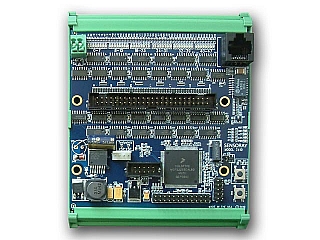
48-channel digital I/O interface w/Ethernet | Model 2410
- Controls/monitors 48 digital signals over Ethernet
- PWM output mode
- Programmable input debounce
- Input edge detection with asynchronous host notification
- Compatible with standard solid state relay racks
- Embedded HTTP and Telnet servers
Description
Model 2410 is a compact open-frame module that interfaces 48 general-purpose TTL/CMOS compatible digital input/output (DIO) signals to Ethernet. It features edge detection, a PWM output mode and other functions that offload work from the host computer in measurement and control applications.
2410 block diagram
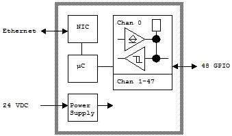
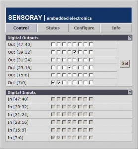
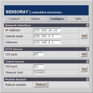
The module communicates through its built-in web and telnet servers, using telnet for automation applications and an embedded web site for configuration, manual control, and diagnostics. Precompiled API libraries are provided for Linux and Windows, along with open source (C language) code to enable porting and customization.
2410 web screenshots
The unit has a small footprint, requires only a single 24VDC power source, and can be quickly and easily mounted by snapping it onto a standard DIN mounting rail. It will interface directly to many standard solid state relay racks, and it has an auxiliary power output that is capable of supplying 5VDC power to solid state relay racks or other modest external loads.
DIO Functions
Each open-collector DIO channel can operate as an input, an output, or in wired-or mode. A number of special functions such as debounce, edge detection, and PWM output, are available on each channel. All channels are synchronized to a common 1KHz clock to guarantee true state machine behavior. An LED indicates each channel's physical state.
Block diagram of one DIO channel
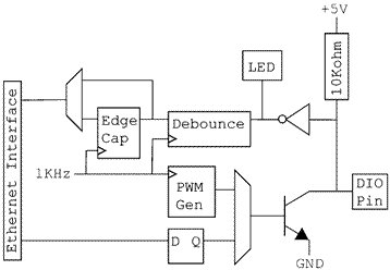
Software debounce can be enabled for any input signal, with debounce interval ranging from 0 to 255 milliseconds. Also, edge detection and capture may be enabled for any input signal and, if desired, asynchronous notification messages (i.e., "interrupts") will be sent to an Ethernet client when edge events are captured.
Outputs are capable of 24mA active-low output drive, and internal pull-up resistors are provided for all channels. Each output channel may be independently configured to function in the conventional fashion (directly controlled by Ethernet clients) or as a PWM generator with one millisecond resolution.
Signal Connections
A standard 50 pin header is provided for connecting the module to external breakout boards, solid-state relay racks or custom OEM signal distribution systems.
Model 2410 controlling a solid state relay rack
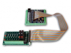
Model 2410 with a 7505TDIN screw terminal breakout board
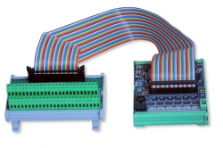
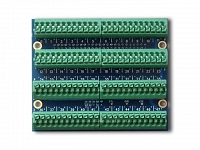
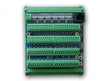
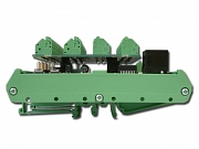
Sensoray also offers the Model 2410TA termination board, which can be top-mounted to the module to add convenient field wiring terminal blocks without enlarging the module's footprint. The spring-loaded terminals allow quick connection of 24-16 gauge wires.
Model 2410TA zero-footprint, top-mounting termination board
LabVIEW Demo
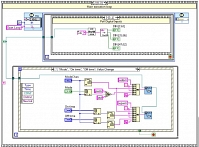
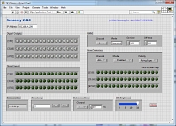
In addition to the standard API, Sensoray provides a LabVIEW application which demonstrates how to interact with the 2410.
2410 LabVIEW demo software
Specifications
| General Purpose Digital I/O | ||
|---|---|---|
| Digital Inputs | Input type | 5V TTL/CMOS compatible |
| Off state input voltage | +2.0 to +5.25 VDC | |
| On state input voltage | 0.0V to +0.8 VDC | |
| Input impedance | 10 kΩ | |
| Sample rate | 1 KHz | |
| Debounce period | 0 to 255 ms, 1ms resolution | |
| Digital Outputs | Output type | Active low, open collector with 10 kΩ pullup resistor to internal 5V |
| Output current, on state | 24mA maximum | |
| PWM resolution | 1 ms on-time, 1 ms off-time (max. frequency = 500 Hz) | |
| Communications Interface | ||
| Network | Physical layer | 10BaseT, 100BaseTx Ethernet |
| Bit rate | 10/100 Mbps, auto-detecting | |
| Isolation | 1500Vrms | |
| Protocols | ARP, HTTP, ICMP, IPv4, TCP, Telnet | |
| Configuration | Programmable via HTTP (static ARP): IP address, netmask, gateway | |
| HTTP Server | Concurrent sessions | 1 |
| Functions | Status, configuration, I/O monitor/control | |
| TELNET Server | Concurrent sessions | 3 |
| Inactivity timeout | 5 minutes (default, programmable via HTTP), programmable per session | |
| Power and Environmental | ||
| Module Power | Input power | 24VDC ±5% @90mA (digital outputs off, no external loads) |
| Auxiliary Power Output | Voltage | +5VDC &plusn;5%, referenced to module input power supply return |
| Current | 400 mA maximum | |
| Temperature | Operating range | -25 to 85 °C |
| Mechanical | ||
| Module Dimensions | Outer dimensions | (W x H x D): 4.1 x 5.0 x 2.2 inches
W = overall DIN rail length D = module height from DIN rail back panel; additional clearance required for field wiring. |
| Mating Connectors (not included) | ETH | RJ-45 plug, AMP 554169 or equivalent |
| DIO | 50-pin socket, Tyco 1-1658621-0 or equivalent | |
| AUXPWR | Molex 22-01-3047 with 08-50-0114 pin contact (4), or equivalent | |
Documentation
| File | Version | Date M-D-Y | Type | Size |
|---|---|---|---|---|
| Manuals | ||||
| Model 2410 Instruction Manual | 1.0.1 | 10-17-24 | 250 KB | |
| Model 2410 API Manual | 1.0.0 | 10-17-24 | 537 KB | |
| Application notes | ||||
| Model 2410 Command Line Protocol Telnet command line functions | — | 10-17-24 | 104 KB | |
| Model 2410 tech support wiki FAQs, examples and additional information | — | — | HTML | — |
| Other | ||||
| Model 2410 Dimensions | 1.0.0 | 10-17-24 | 242 KB | |
Downloads
| File | Version | Date M-D-Y | Type | Size |
|---|---|---|---|---|
| Model 2410 Software Development Kit (SDK) For Linux and Windows | 1.1.2 | 10-17-24 | ZIP | 1.78 MB |
| Model 2410 LabVIEW Demo Including LabVIEW VIs | 1.0.0 | 10-17-24 | ZIP | 136 KB |
| Other Operating Systems | ||||
| Need a software development kit for another operating system? We can port our SDK to your OS for a NRE fee or, with a volume commitment, at no additional cost. Contact Sales for details. | ||||


