Industrial I/O via Ethernet | Model 2600 Series
- Connects wide variety of real world signals to Ethernet
- Highly expandable - 100's of I/O points on one LAN port
- Low cost, DIN rail mountable modules
- Integrated safety interlock circuitry
- Field wiring connects directly to I/O boards
- Integral power distribution system
Description
The 2600 series is a low-cost, DIN rail mountable, modular measurement and control system designed for applications such as machine control, industrial process control, building automation and remote data acquisition. It connects a virtually limitless number of I/O measurement and control points to Ethernet, thereby enabling a remote computer to monitor and control the I/O system over a LAN.
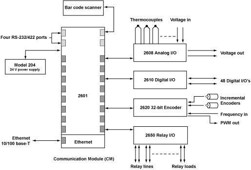
Example 2600 system

A basic system is made from a model 2601 communication module, a model 204 or equivalent 24VDC power supply, and an Ethernet connection. Up to sixteen I/O modules can be connected to the 2601 to provide interface types and quantities as needed. When fully expanded, one 2601 can provide access to hundreds of I/O points. More complex systems can be created by connecting two or more 2601s to a LAN through an Ethernet switch, with up to sixteen additional I/O modules per 2601.
Use the Design Assistant to quickly design a system and calculate pricing. |
Modules
At the heart of every 2600 system is a model 2601 communication module. The 2601 distributes power, interlock signals, and communications to as many as sixteen I/O modules. It also includes four RS-232/422/485 COM ports for communicating with serial devices such as barcode scanners.
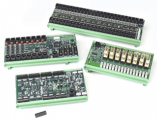
A variety of I/O module types are available, each with a specialized function:
| Model | Type | Function |
|---|---|---|
| 2601 | Communication module | Ethernet interface for I/O system; 4 COM ports; supports up to 16 I/O modules |
| 2608 | Analog I/O | 16 analog in, up to 8 analog out — measures voltage, thermocouples, 4-20 mA loops |
| 2610 | Digital I/O | 48 digital I/Os, 5 to 24 VDC, input debounce filters, PWM output mode |
| 2612 | Analog input | 4 strain gauge / RTD |
| 2620 | Counter | 4 incremental encoder / event counter / frequency counter (32 bits) |
| 2650 | Mechanical relay rack | Controls up to 8 mechanical relays, 0V to 240V @ 10A |
| 2652 | Solid state relay rack | Monitors/controls up to 8 SSRs |
| 2653 | Solid state relay rack | Monitors/controls up to 16 SSRs |
A low-cost, Category-5 patch cable connects each I/O module to the 2601. Any combination of I/O modules may be connected to the 2601. All I/O modules employ POL power supplies and optically-isolated communication circuits to avoid problematic ground loops.
Field Wiring
All 2600 series modules employ two-piece mating connectors for quick connections to field wiring—external termination boards are not required. This helps to minimize the need for intermediate termination systems and wiring, thereby reducing both material and assembly costs.
Mechanical
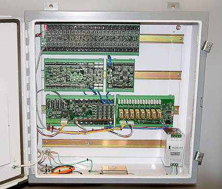
Series 2600 modules are supplied as DIN rail mountable, open-frame circuit boards. They are designed to quickly snap onto standard 35-mm DIN rails, thus simplifying installation and lowering installation costs. Field wiring connectors are conveniently located at module edges for easy cable routing into adjacent wiring ducts. Together, the low module profile and baseboard-mounted connectors eliminate the need for expensive, top-heavy module enclosures found on many competing products.
2600 I/O system mounted in a NEMA enclosure

Power and Interlock Daisy-Chain
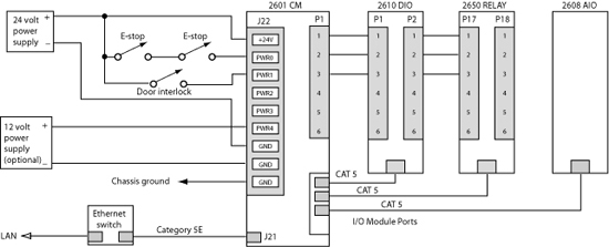
Most I/O modules obtain both operating and I/O power from the 2601 via the Category-5 patch cables that interconnect them. Exceptions to this are the relay and digital I/O modules, which obtain I/O power separately through a power daisy-chain connector. Power enters the 2600 system daisy chain at a dedicated terminal block on the 2601 communication module, which monitors and can report power status to network clients.
Example using multiple I/O supplies and safety interlock switches

The power daisy chain carries up to six different power sources ranging from +5V to +24V, which may be either continuous or interruptible. Each I/O point can be powered from any of the daisy chained power sources. In the case of digital I/O circuits (model 2610), this allows different channels to operate at different voltages. For example, some channels could operate from 5V power while others operate from 12V power (requires external 5 and 12 VDC power supplies).
When an interruptible power source is used, all relay and digital outputs powered by the source will automatically deactivate when power is removed (e.g., when a safety interlock or emergency stop opens). This can be used to ensure fail-safe deactivation when safety conditions require it.
Multiple Ethernet Clients
The 2600 system can be simultaneously accessed by up to four LAN hosts. For example, a laptop can be connected to the LAN to monitor the I/O system and obtain diagnostic information without interrupting the control computer. Or, multiple control computers can interact with a single 2601, with each controlling its own private I/O resources.
Software
Full-featured Windows and Linux API libraries are available for the 2600 series, along with comprehensive sample programs.
Documentation
| File | Version | Date M-D-Y | Type | Size |
|---|---|---|---|---|
| Manuals | ||||
| 2600 Hardware Manual | 2.0.2 | 10-17-24 | 489 KB | |
| 2600 Programming Guide | 1.12.0 | 10-17-24 | 232 KB | |
| Application Notes | ||||
| Tech support wiki for 2600 family | — | — | HTML | — |
Downloads
| File | Version | Date M-D-Y | Type | Size |
|---|---|---|---|---|
| 2600 Software Development Kit For Linux and Windows | 1.1.18 | 10-17-24 | ZIP | 2.04 MB |
| 2600 Labview Drivers | 1.0.0 | 10-17-24 | ZIP | 542 KB |
| Other Operating Systems | ||||
| Need a software development kit for another operating system? We can port our SDK to your OS for a NRE fee or, with a volume commitment, at no additional cost. Contact Sales for details. | ||||
Pricing & Ordering
Use the Design Assistant to quickly design a system and calculate pricing. |


