518
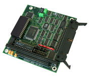
Model 518 is an advanced, eight-channel sensor measurement system on a PC/104 board. It provides excitation for passive sensors and signal conditioning for thermocouples, RTDs, thermistors, and strain and pressure gauges. Each channel can be individually configured to measure voltage, resistance, or any supported sensor type.
-12V power supply
- My SBC doesn't provide -12V power to the PC/104 stack. Does the 518 require -12V power?
Yes, model 518 requires -12V power. Unfortunately, as you have discovered, some SBC systems omit the -12V supply even though it's required by the PC/104 specification.
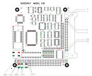
You can check for the presence of the three required power supply voltages (+5V, +12V, -12V) by probing the test points shown in the image on the right. If -12V is missing then you must connect a -12V power supply to your SBC, which in turn must apply the -12V to the stack in conformance with the PC/104 specification. When you do this, be sure to connect the positive terminal of the -12V supply to your +5V/+12V returns so that all three supplies share a common ground.
Many SBC's provide a connector pin or terminal block for -12V. Please refer to your SBC documentation for details, or contact the SBC manufacturer if this is not covered in the documentation.
Sensor data is all zeroes
- Sensor data is all zeroes after a reset. What could be the problem?
First verify that you have applied the required power supply voltages to the board. If so, the problem may be caused by not waiting long enough after a board reset.
An A/D conversion is not invoked when you fetch sensor data; this simply returns the most recently acquired sample. If no conversions have been performed yet, the sensor data will be zero. When the board is reset, it will perform a calibration cycle before it starts scanning sensors. So, after a reset, you must wait long enough for a calibration cycle, plus a complete scan of all sensors, before you will be able to read valid data (approximately 350 ms).
Connector pinout
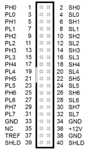
The connector pinout shown to the right is used by model 518 and all other Sensoray Smart A/D boards except model 417.
For each sensor channel x (where x is in the range 0:7):
- PHx/PLx supply excitation to a passive sensor, if needed
- SHx/SLx are the differential analog inputs
TREF and +12V should only be used to supply operating power to an external thermocouple cold junction compensation sensor, which is unnecessary if thermocouples are not being measured.


