Difference between revisions of "826 demo (VB.NET)"
(+link to 826 main page) |
(→Counter tab) |
||
| Line 155: | Line 155: | ||
** Count Enable - enable_counting trigger (TE bits); see S826_CounterModeRead, S826_CounterModeWrite | ** Count Enable - enable_counting trigger (TE bits); see S826_CounterModeRead, S826_CounterModeWrite | ||
** Count Disable - disable_counting trigger (TD bits); see S826_CounterModeRead, S826_CounterModeWrite | ** Count Disable - disable_counting trigger (TD bits); see S826_CounterModeRead, S826_CounterModeWrite | ||
| + | |||
| + | [[Category:826|demo]] | ||
Latest revision as of 11:06, 4 June 2020
To jump-start your model 826 project, we offer a comprehensive demo program that provides a GUI for nearly every hardware resource on the board. A pre-built executable is included to allow you to immediately configure and exercise the board's I/O interfaces. All VB.NET source files are provided, including a reusable module (mid826.vb) that declares all functions, types, and constants for the 826 API.
Contents |
[edit] Installation
The demo software is automatically installed when you run the Windows Software Development Kit (SDK) installer. If you haven't already done so, download and install the SDK, which is available here on the Downloads tab.
[edit] Starting the program
You may start the demo program in either of the following ways:
- Double-click the demo's desktop shortcut, which was created by the SDK installer
- Open the VisualStudio project (app-826-win-vb.sln) and run the demo in the VB.NET development environment
[edit] Introduction
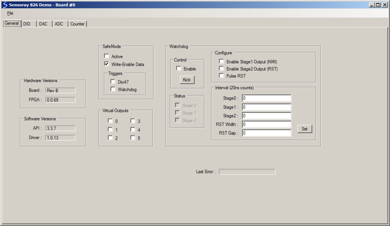
The demo program has a single window containing a system of tabs. Each tab is a collection of GUI controls related to a particular I/O subsystem. The General tab covers several subsystems (watchdog, safemode controller, and virtual digital outputs) and also displays version information.
A specific 826 board must be selected for use with the demo program. If only one board is detected by the driver, it will be automatically selected and the tab system will appear when the demo starts. If multiple boards are installed, a dialog box will be displayed when the program starts which shows the IDs of all detected boards (set by board switches); you may select one board, whereupon the tab system will appear. The ID of the selected board appears at the top of the demo window (e.g., "Board #0").
When the tab system is first displayed, all GUI controls are initialized to indicate the current board state. The board state is not changed in any way when the demo program starts or terminates; consequently, the program can be terminated and restarted without disturbing the board's configuration or operation.
Multiple instances of the demo are allowed to run concurrently. Typically, the board selected by an instance will not also be selected by another instance, however this is permitted because the API is process- and thread-safe.
Since board state is preserved upon demo startup/termination and the API is process-safe, you can run your own application software while the demo is running. This is useful when you're debugging your application, as it allows you to monitor and change hardware states with the demo while running your own software.
Most of the GUI controls are associated with API functions, as noted in the following sections. Please refer to the 826 technical manual for information about the API functions and hardware, and to the 826 technical wiki for application examples.
[edit] General tab
- Hardware Versions
- Board - PWB revision letter; see S826_VersionRead
- FPGA - firmware version number; see S826_VersionRead
- Software Versions
- API - middleware version number; see S826_VersionRead
- Driver - device driver version number; see S826_VersionRead
- SafeMode
- Active - click to manually control safemode (SAF bit), automatically activated by watchdog; see S826_SafeControlRead, S826_SafeControlWrite (note:
Write-Enable Datamust be checked to enable writes) - Write-Enable Data - enables writing to safemode-protected resources (SWE bit); see S826_SafeWrenRead, S826_SafeWrenWrite
- Triggers
- Dio47 - enable dio47 triggering (XSF bit); see S826_SafeControlRead, S826_SafeControlWrite (note:
SafeMode|Write-Enable Datamust be checked to enable writes) - Watchdog - enable watchdog triggering (SEN bit); see S826_WatchdogConfigRead, S826_WatchdogConfigWrite (note:
SafeMode|Write-Enable Datamust be checked to enable writes)
- Dio47 - enable dio47 triggering (XSF bit); see S826_SafeControlRead, S826_SafeControlWrite (note:
- Virtual Outputs
- 0-5 - see S826_VirtualRead, S826_VirtualWrite
- Watchdog
- Control
- Enable - enable/disable watchdog; see S826_WatchdogEnableRead, S826_WatchdogEnableWrite (note:
SafeMode|Write-Enable Datamust be checked to enable writes) - Kick - click to kick watchdog; see S826_WatchdogKick
- Enable - enable/disable watchdog; see S826_WatchdogEnableRead, S826_WatchdogEnableWrite (note:
- Status | 0-2 - timeout status of watchdog timer stages; see S826_WatchdogStatusRead
- Configure
- Enable Stage1 Output - NIE bit; see S826_WatchdogConfigRead, S826_WatchdogConfigWrite (note:
SafeMode|Write-Enable Datamust be checked to enable writes) - Enable Stage2 Output - OEN bit; see S826_WatchdogConfigRead, S826_WatchdogConfigWrite (note:
SafeMode|Write-Enable Datamust be checked to enable writes) - Pulse RST - PEN bit; see S826_WatchdogConfigRead, S826_WatchdogConfigWrite (note:
SafeMode|Write-Enable Datamust be checked to enable writes)
- Enable Stage1 Output - NIE bit; see S826_WatchdogConfigRead, S826_WatchdogConfigWrite (note:
- Interval - watchdog time intervals; see S826_WatchdogConfigRead, S826_WatchdogConfigWrite (note:
SafeMode|Write-Enable Datamust be checked to enable writes)
[edit] DIO tab
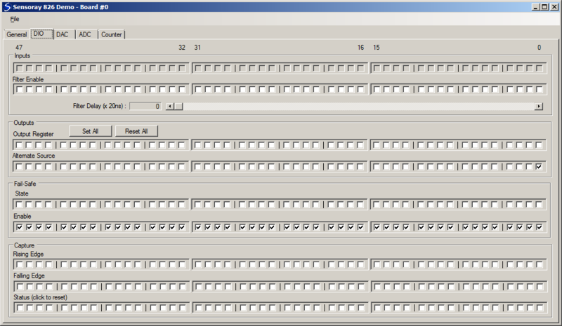
- Inputs
- Top row of checkboxes indicate pin states, which are automatically polled by the demo; see S826_DioInputRead
- Filters - enables for debounce/noise filters; see S826_DioFilterRead, S826_DioFilterWrite
- Filter Delay - filter time for debounce/noise filters; see S826_DioFilterRead, S826_DioFilterWrite
- Outputs
- Set All - turn on all 48 DIO output drivers (drive to 0V)
- Reset All - turn off all 48 DIO output drivers (pull up to +5V)
- Output Register - DIO output driver states; see S826_DioOutputRead, S826_DioOutputWrite (using S826_BITSET and S826_BITCLR modes, to allow a board to be selected by multiple instances of the demo program)
- Alternate Source - see S826_DioOutputSourceRead, S826_DioOutputSourceWrite (note:
General|SafeMode|Write-Enable Datamust be checked to enable writes)
- Fail-Safe
- State - see S826_DioSafeRead, S826_DioSafeWrite (note:
General|SafeMode|Write-Enable Datamust be checked to enable writes) - Enable - see S826_DioSafeEnablesRead, S826_DioSafeEnablesWrite (note:
General|SafeMode|Write-Enable Datamust be checked to enable writes)
- Capture
- Rising Edge - enable rising edge capture; see S826_DioCapEnablesRead, S826_DioCapEnablesWrite
- Falling Edge - enable falling edge capture; see S826_DioCapEnablesRead, S826_DioCapEnablesWrite
- Status - indicates captured edge (click to clear); see S826_DioCapRead
[edit] DAC tab
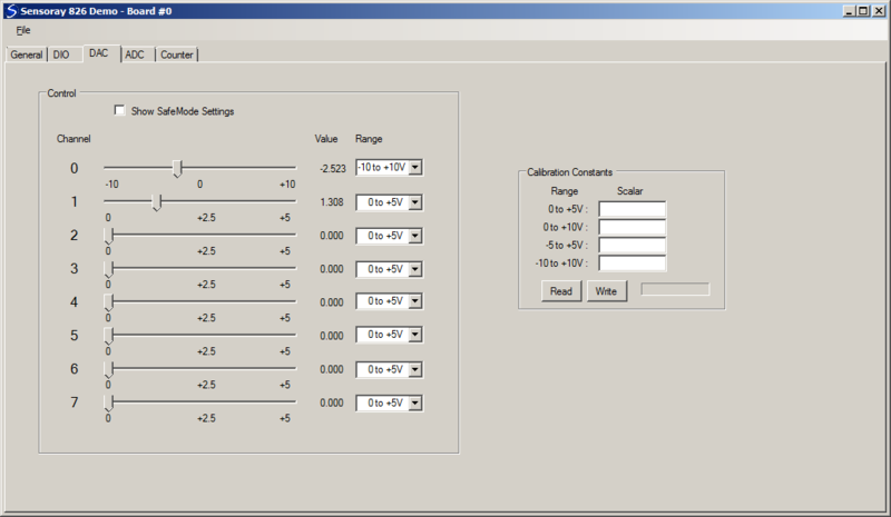
- Control
- Show SafeMode Settings - allows channel controls (below this control) to display/modify safemode (vs. normal mode) settings
- Sliders - controls output setpoint; see S826_DacRead, S826_DacDataWrite (note:
General|SafeMode|Write-Enable Datamust be checked to enable writes to safemode setpoint) - Value - shows output setpoint in Volts
- Range - controls output range; see S826_DacRead, S826_DacRangeWrite (note:
General|SafeMode|Write-Enable Datamust be checked to enable writes to safemode range)
- Calibration Constants
- Consult Sensoray for details; do not click Write as it may corrupt the board's calibration!
[edit] ADC tab
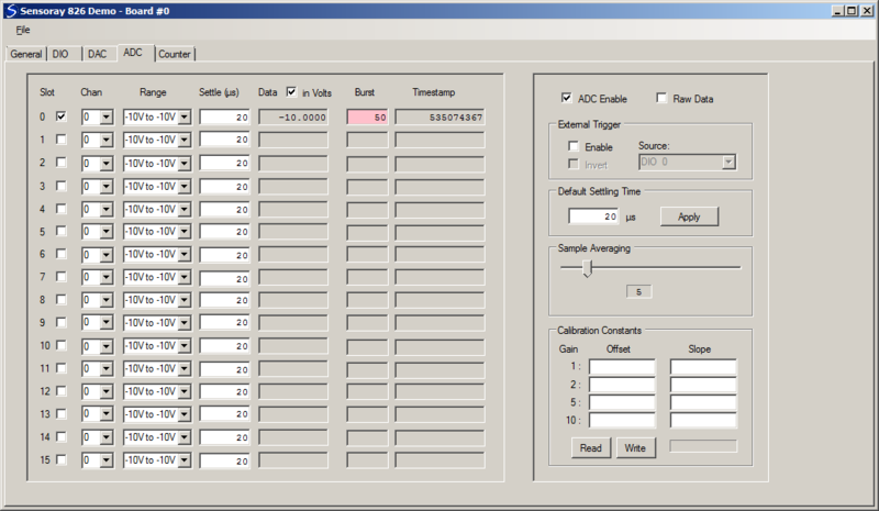
- Slot info (left control group)
- Slot enable checkbox - adds slot to slotlist; see S826_AdcSlotlistRead, S826_AdcSlotlistWrite
- Chan - analog input channel; see S826_AdcSlotConfigRead, S826_AdcSlotConfigWrite
- Range - analog input range; see S826_AdcSlotConfigRead, S826_AdcSlotConfigWrite
- Settle - settling time in microseconds; see S826_AdcSlotConfigRead, S826_AdcSlotConfigWrite
- Data - measured sample data; see S826_AdcRead
- in Volts - display data in Volts (vs. binary)
- Burst - burst ID (red indicates sample buffer overflow); see S826_AdcRead
- Timestamp - time when analog input was sampled; see S826_AdcRead
- General (right control group)
- ADC Enable - enable A/D conversions; see S826_AdcEnableRead, S826_AdcEnableWrite
- Raw Data - display uncorrected (vs. cal-corrected) data
- External Trigger
- Enable - trigger bursts from signal (vs. free-running back-to-back bursts); see S826_AdcTrigModeRead, S826_AdcTrigModeWrite
- Source - trigger signal source (when Enable checked); see S826_AdcTrigModeRead, S826_AdcTrigModeWrite
- Invert - invert trigger signal (when Enable checked); see S826_AdcTrigModeRead, S826_AdcTrigModeWrite
- Default Settling Time - to establish uniform settling time for all slots, enter time and click Apply; see S826_AdcSlotConfigWrite
- Sample Averaging - number of samples to average for each displayed Data value
- Calibration Constants - consult Sensoray for details; do not click Write as it may corrupt the board's calibration!
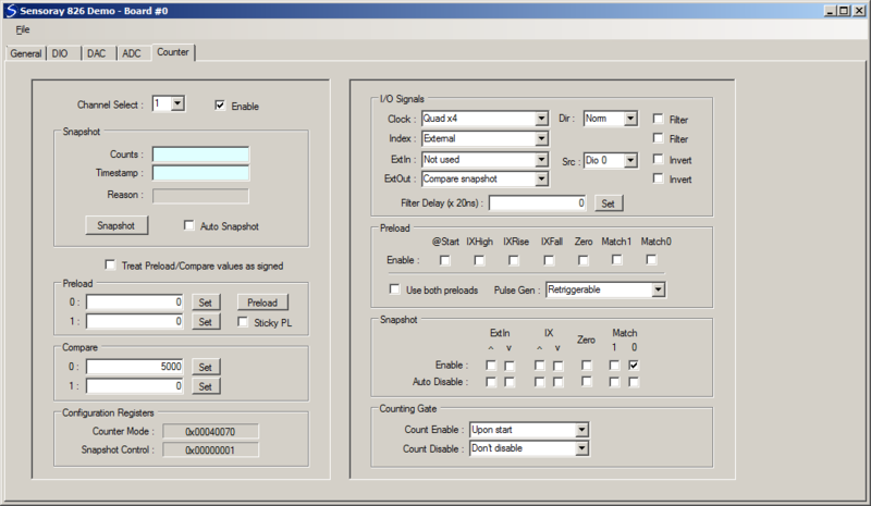
[edit] Counter tab
- Left control group
- Channel Select - select counter to display and control (all controls are updated when channel is changed, to indicate selected counter's settings)
- Enable - enable/disable counter; see S826_CounterStatusRead, S826_CounterStateWrite
- Snapshot
- Counts/Timestamp/Reason - most recent snapshot
- Snapshot button - click to invoke a soft snapshot; see S826_CounterSnapshot
- Auto Snapshot - periodically invoke soft snapshots to get "automatic" counts updates
- Treat Preload/Compare values as signed - (vs. unsigned integers)
- Preload
- Value fields - enter value and click Set to write it to a preload register; see S826_CounterPreloadRead, S826_CounterPreloadWrite
- Preload button - copy preload0 value into the counter; see S826_CounterPreload
- Sticky PL - perform continuous (vs. pulsed) preload; see S826_CounterPreload
- Compare
- Value fields - enter value and click Set to write it to a compare register; see S826_CounterCompareRead, S826_CounterCompareWrite
- Configuration Registers - these change dynamically with counter configuration; useful when coding calls to S826_CounterModeWrite and S826_CounterSnapshotConfigWrite
- Right control group
- I/O Signals
- Clock/Dir - Clock input source (K bits) and count direction (UD bit); see S826_CounterModeRead, S826_CounterModeWrite
- Index - Index input source (XS bits); see S826_CounterModeRead, S826_CounterModeWrite
- ExtIn/Src/Invert - ExtIn function , input source and polarity; see S826_CounterModeRead, S826_CounterModeWrite
- ExtOut/Invert - ExtOut function and polarity; see S826_CounterModeRead, S826_CounterModeWrite
- Filter Delay/checkboxes - Filter time and enables; see S826_CounterFilterRead, S826_CounterFilterWrite
- Preload
- Enable - enable preload trigger (TP bits); see S826_CounterModeRead, S826_CounterModeWrite
- Use both preloads - BP bit in mode register; see S826_CounterModeRead, S826_CounterModeWrite
- Pulse Gen - NR bit in mode register; see S826_CounterModeRead, S826_CounterModeWrite
- Snapshot
- Enable - enable snapshot triggers (E flags); see S826_CounterSnapshotConfigRead, S826_CounterSnapshotConfigWrite
- Auto Disable - automatically disable trigger upon snapshot (R flags); see S826_CounterSnapshotConfigRead, S826_CounterSnapshotConfigWrite
- Counting Gate
- Count Enable - enable_counting trigger (TE bits); see S826_CounterModeRead, S826_CounterModeWrite
- Count Disable - disable_counting trigger (TD bits); see S826_CounterModeRead, S826_CounterModeWrite
