Difference between revisions of "2410"
(→Recommended practice) |
(→Power terminal block: content -> link) |
||
| (2 intermediate revisions by one user not shown) | |||
| Line 173: | Line 173: | ||
* Wire ferrules of diameter 0.5 to 1.0 mm. | * Wire ferrules of diameter 0.5 to 1.0 mm. | ||
| − | + | For more information, see [[Terminal block connections, recommended practice]]. | |
| − | + | ||
| − | + | ||
| − | + | ||
| − | + | ||
| − | + | ||
| − | + | ||
| − | + | ||
| − | + | ||
| − | + | ||
| − | + | ||
| − | + | ||
==Software examples== | ==Software examples== | ||
Latest revision as of 09:11, 10 March 2022
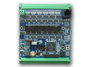
Model 2410 is a compact open-frame module that interfaces 48 general-purpose TTL/CMOS digital input/output (DIO) signals to Ethernet. It features edge detection, PWM output mode and other functions that offload work from the host computer in measurement and control applications.
Contents |
[edit] Telnet
[edit] Timeouts
- I disabled the 2410 communication watchdog timer but the connection still times out after 5 minutes. Why is this happening?
The 2410's communication watchdog is disabled by sending a wto 0 command. However, most telnet clients also have their own inactivity timer, which is set to a default interval (typically 5 minutes). Consequently, the telnet client will independently close the connection when the session is idle for longer than its own timer interval. To resolve this, you must reconfigure your telnet client to use a different interval.
[edit] Remote echo
- The 2410 seems to be retransmitting every TCP packet. Why is this happening?
By default, the 2410 echoes all incoming data. To turn off the remote echo function, have your telnet client issue an IAC DONT ECHO command to the 2410.
[edit] Command line functions
- Where can I find information about the 2410's telnet commands?
For detailed information about telnet commands, please see Sensoray Model 2410 Command Line Protocol.
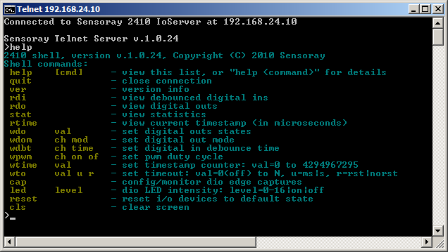
If you are manually controlling a 2410 via telnet and you just need a quick list of available commands, type 'help' at the shell prompt and hit return. When you do this you will see something like the following:
For more specific information about a particular command, type 'help <command>' and hit enter. For example, for information about the wdo (write digital outputs) command, type 'help wdo'.
[edit] How to connect loads
All DIO signals are conveyed through 7410 header J2. A DIO signal is active-low and therefore should be connected to the negative input of its load. For example, when interfacing to a solid-state relay (SSR), connect the DIO signal to the SSR's "-" logic pin.
Loads also require a connection to +5 V (e.g., the "+" logic pin of an SSR). It is recommended to supply this from an external 5 VDC power supply which shares a common ground with the 2410 module (available at J2 pin 50). Alternatively, if only a small amount of load current is needed, you can obtain +5 V directly from the 2410 module, at J4 pin 1 or J5 pins 1-8.
[edit] Using a 2410TA
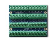
Model 2410TA is a compact breakout board that plugs directly onto a 2410 module. It has two spring-activated terminals per DIO which accept 16- to 24-gauge wires. For each DIO, the silkscreen legend indicates the DIO number and its "+" and "-" terminals. The "+" terminal conveys +5 VDC and the "-" terminal conveys the active-low DIO signal.
To connect a model 2410TA to a load:
- Route the "+" terminal to the load's positive input and route the "-" terminal to the load's negative input.
- The load's positive and negative inputs should only connect to the 2410TA "+" and "-" terminals; they must not connect to any other circuit nets in your system.
- The load must not draw more than 24 mA (load input resistance must be > 208 Ω).
[edit] Relay racks
Model 2410 is pin-compatible with most standard solid-state (SSR) relay racks. Use a 50-conductor flat cable to connect the 2410 module to a relay rack.
An output SSR (AC or DC) is controlled by writing to the associated GPIO, whereas an input SSR (AC or DC) is monitored by reading the GPIO. Model 2410 GPIOs employ active-low logic, and relay racks typically employ active-low signaling. Consequently, you must write '1' to a GPIO to turn on an output SSR and write '0' to turn it off. Similarly, when reading the GPIO or an input SSR, '1' indicates the SSR is on and '0' indicates off.
[edit] 7501Tx
For applications that use up to 24 SSRs it is recommended to use Sensoray model 7501T8, 7501T16 or 7501T24 relay racks. See Using 7501Tx relay racks with model 2410 for further details.
[edit] Others
Various third-party relay racks are available for applications that use more than 24 SSRs.
For example, SSR-RACK48 supports up to 48 SSRs (up to 12 quad SSRs). To use this rack with model 2410, you must provide an external 5 VDC power supply (see this for details). The table below shows the GPIO associated with each SSR (note: columns can be sorted to show ordered SSR-GPIO mappings).
| Header Pin |
SSR Socket |
2410 GPIO |
|---|---|---|
| 1 | 32 | 31 |
| 2 | 31 | 30 |
| 3 | 30 | 29 |
| 4 | 29 | 28 |
| 5 | 28 | 27 |
| 6 | 27 | 26 |
| 7 | 26 | 25 |
| 8 | 25 | 24 |
| 9 | 40 | 39 |
| 10 | 39 | 38 |
| 11 | 38 | 37 |
| 12 | 37 | 36 |
| 13 | 36 | 35 |
| 14 | 35 | 34 |
| 15 | 34 | 33 |
| 16 | 33 | 32 |
| 17 | 48 | 47 |
| 18 | 47 | 46 |
| 19 | 46 | 45 |
| 20 | 45 | 44 |
| 21 | 44 | 43 |
| 22 | 43 | 42 |
| 23 | 42 | 41 |
| 24 | 41 | 40 |
| 25 | 8 | 7 |
| 26 | 7 | 6 |
| 27 | 6 | 5 |
| 28 | 5 | 4 |
| 29 | 4 | 3 |
| 30 | 3 | 2 |
| 31 | 2 | 1 |
| 32 | 1 | 0 |
| 33 | 16 | 15 |
| 34 | 15 | 14 |
| 35 | 14 | 13 |
| 36 | 13 | 12 |
| 37 | 12 | 11 |
| 38 | 11 | 10 |
| 39 | 10 | 9 |
| 40 | 9 | 8 |
| 41 | 24 | 23 |
| 42 | 23 | 22 |
| 43 | 22 | 21 |
| 44 | 21 | 20 |
| 45 | 20 | 19 |
| 46 | 19 | 18 |
| 47 | 18 | 17 |
| 48 | 17 | 16 |
| 49 | — | NC |
| 50 | — | GND |
[edit] Power terminal block
24 VDC power is connected to the board via a two-pin terminal block (TB). The TB is a Phoenix PN 1985195 or equivalent.
The TB accepts:
- 20 to 16 AWG conductors, with a recommended stripping length of 8 mm.
- Wire ferrules of diameter 0.5 to 1.0 mm.
For more information, see Terminal block connections, recommended practice.
[edit] Software examples
[edit] Ethernet GPIO bridge
This C example shows how to send 48 GPIO signals over Ethernet using two 2410 modules. The input signals are applied to the first 2410 module, which is assigned IP address 192.168.24.10. The client periodically reads the input signal states and sends them over Ethernet to a second 2410 module, which is assigned address 192.168.41.11. Note that error checking has been omitted for clarity; it is recommended to always use error checking in production code.
#include "224xx.h"       // API header file

HSESSION rsess, wsess;   // session handles
u32 err = ERR_NONE;      // error code
u16 states[3];           // GPIO states

s24xx_ApiOpen();                                                  // Open the API.
s24xx_SessionOpen(&rsess, &err, 2410, "192.168.24.10", 23, 1000); // Start session on the first module.
s24xx_SessionOpen(&wsess, &err, 2410, "192.168.24.11", 23, 1000); // Start session on the second module.
while (1) {                               // Repeat forever:
  Sleep(100);                             //   Pause for 100 milliseconds.
  s2410_ReadDin(rsess, &err, states);     //   Sample the GPIO input signals on the first module.
  s2410_WriteDout(wsess, &err, states);   //   Output the GPIO signals on the second module.
}
[edit] C# example
For a simple C# programming example, have a look at this VS project.
[edit] Maximum output current
DIOs are subject to two different maximum current limits: individual and group. Each DIO is capable of continuously sinking up to 24 mA; this is the maximum individual current. However, it's not permitted for all DIOs to do this simultaneously because this would exceed the maximum group current.
DIO channels are organized into groups as shown below. In any particular group, the group current is the total of all individual currents in the group. For example, in Group4 the group current is the sum of the currents flowing in DIO24 through DIO29.
| Group | DIOs |
|---|---|
| 0 | 0-5 |
| 1 | 6-11 |
| 2 | 12-17 |
| 3 | 18-23 |
| 4 | 24-29 |
| 5 | 30-35 |
| 6 | 36-41 |
| 7 | 42-47 |
Each group is capable of continuously sinking up to 72 mA. As shown in the following table, all DIOs in a group may be active at the same time if their individual currents are less than or equal to 12 mA (because 6 * 12 ≤ 72). However, when the individual currents are higher than 12 mA, it is not allowed for all DIOs in a group to be active at the same time.
| DIO current (mA) | Maximum number of active DIOs |
|---|---|
| i ≤ 12 | 6 |
| 12 < i ≤ 14.4 | 5 |
| 14.4 < i ≤ 18 | 4 |
| 18 < i ≤ 24 | 3 |


