Difference between revisions of "826 DAC"
(copied content from 826) |
|||
| (4 intermediate revisions by one user not shown) | |||
| Line 1: | Line 1: | ||
| + | This page contains application notes and other information about the Model 826 analog output system. | ||
| + | |||
| + | For other 826-related topics, please go to the [[826|top-level 826 page]]. | ||
| + | |||
| + | ==Connector pinout== | ||
| + | |||
| + | <gallery heights=350px widths=180px> | ||
| + | File:826 pinout J1.gif | ||
| + | </gallery> | ||
| + | |||
==Bipolar transfer functions== | ==Bipolar transfer functions== | ||
| Line 120: | Line 130: | ||
[[File:Vfd wiring no2.gif|center|400px|alt=Don't do this either!]] | [[File:Vfd wiring no2.gif|center|400px|alt=Don't do this either!]] | ||
| − | ==Linux | + | ==Linux demo sine wave generator== |
The Linux sine wave generator demo may experience a timeout and exit with an error code -15 (S826_ERR_FIFOOVERFLOW). This occurs because the priority of the demo thread may be too low for the sample time. Linux is not a RTOS and the process (or interrupt) may be delayed and not complete the DAC output in the specified time. | The Linux sine wave generator demo may experience a timeout and exit with an error code -15 (S826_ERR_FIFOOVERFLOW). This occurs because the priority of the demo thread may be too low for the sample time. Linux is not a RTOS and the process (or interrupt) may be delayed and not complete the DAC output in the specified time. | ||
Latest revision as of 08:22, 21 June 2021
This page contains application notes and other information about the Model 826 analog output system.
For other 826-related topics, please go to the top-level 826 page.
Contents |
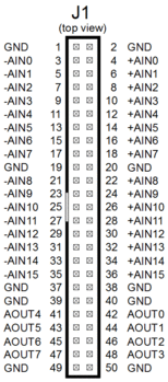
[edit] Connector pinout
[edit] Bipolar transfer functions
In the DAC bipolar output modes (±5 V, ±10 V), the actual voltage range extends slightly beyond the negative end of the indicated output range:
| DAC data | Output (V) |
|---|---|
| 0x0000 | -5.0002 |
| 0x0001 | -5.0 |
| 0x8000 | 0.0 |
| 0xFFFF | +5.0 |
| DAC data | Output (V) |
|---|---|
| 0x0000 | -10.0003 |
| 0x0001 | -10.0 |
| 0x8000 | 0.0 |
| 0xFFFF | +10.0 |
[edit] Specifying setpoint in Volts
- Is there a way to program the analog outputs using Volts units?
The following function will set a DAC output to the specified voltage (note: the function does not check for illegal voltage values that are outside the specified range):
int SetDacOutput(uint board, uint chan, uint range, double volts)
{
  uint setpoint;
  switch (range) {  // conversion is based on dac output range:
    case S826_DAC_SPAN_0_5:   setpoint = (uint)(volts * 0xFFFF /  5);          break; // 0 to +5V
    case S826_DAC_SPAN_0_10:  setpoint = (uint)(volts * 0xFFFF / 10);          break; // 0 to +10V
    case S826_DAC_SPAN_5_5:   setpoint = (uint)(volts * 0xFFFF / 10) + 0x8000; break; // -5V to +5V
    case S826_DAC_SPAN_10_10: setpoint = (uint)(volts * 0xFFFF / 20) + 0x8000; break; // -10V to +10V
    default:                  return S826_ERR_VALUE;                                  // invalid range
  }
  return S826_DacDataWrite(board, chan, setpoint, 0);  // program DAC output and return error code
}
Many applications use a particular, fixed DAC output range, and never change it. In such cases, the range can be "hard coded" when setting the DAC output. For example, if the application uses the ±10 V range:
// Program board0, dac0 output to -7.35 V
int errcode = SetDacOutput(0, 0, S826_DAC_SPAN_10_10, -7.35); // hard-coded ±10 V range
Other applications may switch ranges dynamically. In such cases, if the current DAC output range is unknown (e.g., upon warm restart), you can call S826_DacRead first to determine the range:
// Program board0, dac0 output to +0.573 V
uint range, setpoint;
S826_DacRead(0, 0, &range, &setpoint, 0);  // Get the active range (and DAC data, which we ignore).
SetDacOutput(0, 0, range, 0.573);          // Now we can set the DAC output without changing the range.
[edit] Setpoint readback
The following function will return a DAC's programmed output voltage. Note that the returned volts may not exactly match the value specified in the last SetDacOutput call because the output voltage can only be programmed to discrete values.
int GetDacOutput(uint board, uint chan, double *volts)
{
  uint range, setpoint;
  int errcode = S826_DacRead(board, chan, &range, &setpoint, 0);     // Get DAC output range & setpoint.
  switch (range) {                                                   // Convert binary setpoint to volts:
    case S826_DAC_SPAN_0_5:   *volts = setpoint            * ( 5.0 / 0xFFFF); break;  // 0 to +5V
    case S826_DAC_SPAN_0_10:  *volts = setpoint            * (10.0 / 0xFFFF); break;  // 0 to +10V
    case S826_DAC_SPAN_5_5:   *volts = (setpoint - 0x8000) * ( 5.0 / 0x7FFF); break;  // -5V to +5V
    case S826_DAC_SPAN_10_10: *volts = (setpoint - 0x8000) * (10.0 / 0x7FFF); break;  // -10V to +10V
  }
  return errcode;
}
// Example usage: Read board0, dac0 programmed output voltage.
double volts;
if (GetDacOutput(0, 0, &volts) == S826_ERR_OK)
  printf("dac0 output is set to %f volts", volts);
else
  printf("error reading dac0");
[edit] Control DAC voltage with an incremental encoder
This example shows how to use an incremental shaft encoder to control a DAC's output voltage.
[edit] Connecting to a VFD
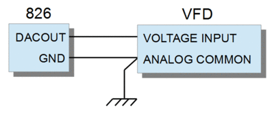
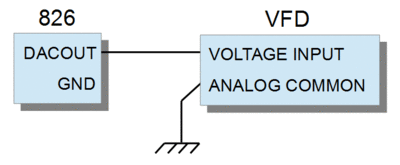
In motor-control applications it's common to use a DAC to generate the control voltage for a variable-frequency drive (VFD). When doing this, it's essential to properly wire the ground signals so as to avoid noise and disruptive ground loops. In particular:
- Connect the VFD analog ground to an 826 GND pin, which is the analog reference for the DAC output signal.
- Do not connect the VFD analog ground net to anything else (e.g., chassis ground).
The recommended wiring shown below uses the DAC's signal ground (826 GND) as analog reference and avoids ground loops and thus ensures accurate, problem-free motor control:
[edit] Linux demo sine wave generator
The Linux sine wave generator demo may experience a timeout and exit with an error code -15 (S826_ERR_FIFOOVERFLOW). This occurs because the priority of the demo thread may be too low for the sample time. Linux is not a RTOS and the process (or interrupt) may be delayed and not complete the DAC output in the specified time.
Older version of the demo will exit when S826_ERR_FIFOOVERFLOW occurs. Later versions of the demo, however, will print an error code and continue outputting the sine wave.
In any case, if the DAC output sampling time requirements are very small and need to be precise, it is recommended to run the process at a higher priority. You may also consider using a low-latency or rt kernel.
To run the demo at a higher priority:
"nice -n 19 ./s826demo"
For Ubuntu low-latency kernel:
"sudo apt-get install linux-lowlatency linux-headers-lowlatency"
For Ubuntu rt kernel:
"sudo apt-get install linux-rt linux-headers-rt"
In extreme high performance cases, you may consider using the raw DAC write command (S826_DacRawWrite) instead of S826_DacDataWrite. You must make sure to understand the DAC ranges before doing so. This should normally not be necessary as S826_DacDataWrite is only marginally slower.
[edit] Short-circuit protection
The board's DAC devices do not have output short-circuit protection. However, each DAC automatically limits its output current to 38 mA. Consequently, a DAC can tolerate intermittent output shorts and will not be damaged as long as the DAC device does not overheat.
[edit] DAC accuracy specification
Resolution and monotonicity are both 16 bits minimum.
| PARAMETER | CONDITIONS | VALUE | UNITS | ||
|---|---|---|---|---|---|
| MIN | TYP | MAX | |||
| Integral Nonlinearity | ±2 | LSB | |||
| Differential Nonlinearity | ±1 | LSB | |||
| Gain Error | ±4 | ±20 | LSB | ||
| Gain Temperature Coefficient | ±2 | ppm/°C | |||
| Unipolar Zero-Scale Error | 5V unipolar range, 25°C 10V unipolar range, 25°C 5V unipolar range 10V unipolar range |
±80 ±100 ±140 ±150 |
±200 ±300 ±400 ±600 |
µV µV µV µV | |
| V_offset Temperature Coefficient | All unipolar ranges | ±2 | µV/°C | ||
| Bipolar Zero Error | All bipolar ranges | ±2 | ±12 | LSB | |


