Difference between revisions of "826 watchdog"
(copied content from 826) |
|||
| (4 intermediate revisions by one user not shown) | |||
| Line 1: | Line 1: | ||
| − | This | + | This page contains application notes and other information about the [[826]] watchdog timer and fail-safe system. |
| + | |||
| + | For other 826-related topics, see the [[826|top-level 826 page]]. | ||
==Activating safemode with an E-stop contact== | ==Activating safemode with an E-stop contact== | ||
| Line 58: | Line 60: | ||
S826_WatchdogConfigWrite(0, 0x10, wdtiming); // Set t0 interval; t0 triggers safemode. | S826_WatchdogConfigWrite(0, 0x10, wdtiming); // Set t0 interval; t0 triggers safemode. | ||
| − | // TODO: [[826#Default safemode states|Program safemode states]] | + | // TODO: [[826 watchdog#Default safemode states|Program safemode states]] |
S826_WatchdogEnableWrite(0, 1); // Start the watchdog running. | S826_WatchdogEnableWrite(0, 1); // Start the watchdog running. | ||
| Line 107: | Line 109: | ||
S826_WatchdogEnableWrite(0, 1); // Start the watchdog (AND START KICKING!) | S826_WatchdogEnableWrite(0, 1); // Start the watchdog (AND START KICKING!) | ||
S826_SafeWrenWrite(0, S826_SAFEN_SWD); // Write-disable protected settings. | S826_SafeWrenWrite(0, S826_SAFEN_SWD); // Write-disable protected settings. | ||
| + | |||
| + | ==Connector P2== | ||
| + | |||
| + | ===Pinout=== | ||
| + | |||
| + | <gallery heights=150px widths=180px perrow=3> | ||
| + | File:826 pinout P2.gif | ||
| + | </gallery> | ||
| + | |||
| + | ===Mating connector=== | ||
| + | |||
| + | These connectors (or equivalents) will mate to the board's three-pin Watchdog Reset Out header (P2): | ||
| + | * Molex 22-01-2037 (ramp only) | ||
| + | * Molex 22-01-3037 (ramp + alignment ribs) | ||
==Turning off the relay== | ==Turning off the relay== | ||
| − | After the watchdog has activated the Reset Out relay, the application program can deactivate the relay by calling <code>S826_WatchdogEnableWrite()</code> with <code>enable=0</code>, as shown below: | + | After the watchdog timer has activated the on-board Reset Out relay, the application program can deactivate the relay by calling <code>S826_WatchdogEnableWrite()</code> with <code>enable=0</code>, as shown below: |
S826_WatchdogEnableWrite(0, 0); // Turn off relay on board0. | S826_WatchdogEnableWrite(0, 0); // Turn off relay on board0. | ||
| Line 136: | Line 152: | ||
} | } | ||
S826_SafeWrenWrite(0, S826_SAFEN_SWD); // Protect safemode data registers. | S826_SafeWrenWrite(0, S826_SAFEN_SWD); // Protect safemode data registers. | ||
| − | |||
| − | |||
| − | |||
| − | |||
| − | |||
| − | |||
Latest revision as of 10:39, 29 January 2021
This page contains application notes and other information about the 826 watchdog timer and fail-safe system.
For other 826-related topics, see the top-level 826 page.
Contents |
[edit] Activating safemode with an E-stop contact
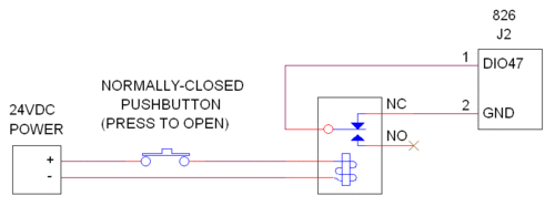
An external emergency stop (E-stop) switch can be used to force analog and digital outputs to fail-safe states. To implement this, you must convert the E-stop signal to active-low TTL/CMOS and apply it to DIO47, so that DIO47 will be driven low when the E-stop button is pressed. The following schematic shows a robust, reliable way to do this for a 24V E-stop contact. This circuit ensures that safemode will be activated if the E-stop pushbutton is pressed, or 24VDC power is lost, or the relay coil opens.
Typically, the application program will configure the fail-safe system during initialization, before I/O operations begin. This is done by programming the analog and digital safemode states, and then "arming" the system by enabling DIO47 to trigger safemode operation. The following example illustrates this process:
// Configure and arm the fail-safe system ---------------

int i;

// The desired fail-safe output conditions (change as required):
uint safeDioEnables[2] = {0x00FFFFFF, 0x00FFFFFF};  // Switch all DIOs to fail-safe states.
uint safeDioData[2]    = {0, 0};                    // Safemode DIO states.
uint safeAoutRange[4]  = {0, 0, 0, 0};              // Safemode analog output ranges.
uint safeAoutLevel[4]  = {0, 0, 0, 0};              // Safemode analog output levels.

// Allow modifications to fail-safe settings.
S826_SafeWrenWrite(0, S826_SAFEN_SWE);

// Program analog output fail-safe conditions.
for (i = 0; i < S826_NUM_DAC; i++) {
  S826_DacRangeWrite(0, i, safeAoutRange[i], 1);
  S826_DacDataWrite(0, i, safeAoutLevel[i], 1);
}

// Program digital output fail-safe conditions.
S826_SafeEnablesWrite(0, safeDioEnables);
S826_DioSafeWrite(0, safeDioData, S826_BITWRITE);

// Allow the E-stop switch to activate fail-safe operation.
S826_SafeControlWrite(0, S826_CONFIG_XSF, S826_BITSET);

// Prevent errant software from modifying fail-safe settings.
S826_SafeWrenWrite(0, S826_SAFEN_SWD);
In many cases the application program must be alerted when the E-stop pushbutton is pressed, so that it can execute relevant tasks (e.g., record the event to an error log). The following example shows how to detect and handle an E-stop event.
// Detect and handle an E-stop pushbutton press ------------

WaitForDioFallingEdge(0, 47); // Wait for DIO47 falling edge.
printf("E-stop pushbutton was pressed!");
[edit] Activating safemode with the watchdog
In many control applications, the analog and digital outputs must automatically switch to safe states if software fails to execute normally. This can be implemented by using watchdog Timer0 to activate safemode. To set this up, configure the watchdog and safemode systems during initialization (before I/O operations begin):
#define WD_MILLISECONDS 100  // Watchdog Timer0 will timeout if unkicked for this long
wdtiming[] = {WD_MILLISECONDS * 50000, 1, 1, 0, 0};

S826_SafeWrenWrite(0, S826_SAFEN_SWE);       // Write-enable watchdog/safemode settings.
S826_WatchdogConfigWrite(0, 0x10, wdtiming); // Set t0 interval; t0 triggers safemode.

// TODO: Program safemode states

S826_WatchdogEnableWrite(0, 1);              // Start the watchdog running.
S826_SafeWrenWrite(0, S826_SAFEN_SWD);       // Write-protect watchdog/safemode settings.
The above code starts the watchdog timer, so the application program must now regularly "kick" the watchdog to prevent a timeout. This is typically done by periodically executing a kick algorithm. The kick algorithm may be simple or complex, depending on the number of running threads and other factors. The simplest algorithm will simply kick the watchdog, unconditionally:
CreateTimer(0, 0, 100000);  // Execute this loop every 100 milliseconds:
while (1) {
  S826_WatchdogKick(0, 0x5A55AA5A);  // Unconditionally kick the watchdog.
  WaitForTimer(0, 0);
}
Here's a slightly more complex version that monitors the states of two other threads (threadA and threadB). When each monitored thread completes its task, it stores a special value in a reserved memory location. The special values, when OR'ed together, form the value required for a watchdog kick.
int a_kick;  // ThreadA stores 0x5A550000 here when it completes.
int b_kick;  // ThreadB stores 0x0000AA5A here when it completes.

CreateTimer(0, 0, 100000);  // Execute this loop every 100 milliseconds:
while (1) {
  S826_WatchdogKick(0, a_kick | b_kick);  // Kick watchdog if both threads completed.
  a_kick = b_kick = 0;                    // Reset completion status.
  WaitForTimer(0, 0);
}
When watchdog timer0 times out, it may be necessary to notify "system health" monitoring software so it can take appropriate corrective action. This is easily done, as shown in the following code:
if (S826_WatchdogEventWait(0, INFINITE_WAIT) == S826_ERR_OK) {
  // Watchdog timer0 timed out, so take appropriate corrective action
}
[edit] Output watchdog on a DIO
The outputs from watchdog timer1 and timer2 can be routed to select DIOs. As explained in the API manual (see S826_DioOutputSourceWrite), timer1 can be routed to DIOs 7, 15, 23, 31, 39 and 47, and timer2 can be routed to DIOs 6, 14, 22, 30, 38 and 46.
The following code will route the output of timer1 to dio7 so that dio7 will be turned on (driven low, to 0 V) when timer1 times out. As always, timer0 is used to time the kicks. Timer1 is assigned a minimum delay (DELAY1=1) so that it will timeout (and thereby activate dio7) one clock (20 ns) after timer0 times out.
#define WD_MILLISECONDS 100  // Watchdog Timer0 will timeout if unkicked for this long

wdtiming[] = {WD_MILLISECONDS * 50000, 1, 1, 0, 0};  // timing parameters
uint routing[] = {1 << 7, 0};                        // mask for dio7

S826_SafeWrenWrite(0, S826_SAFEN_SWE);   // Write-enable protected settings.
S826_WatchdogConfigWrite(0,              // Configure watchdog:
  S826_WD_NIE,                           //   connect timer1 to NMI net
  wdtiming);                             //   set timer0 & timer1 intervals
S826_DioOutputSourceWrite(0, routing);   // Route NMI net to dio7.
S826_WatchdogEnableWrite(0, 1);          // Start the watchdog (AND START KICKING!)
S826_SafeWrenWrite(0, S826_SAFEN_SWD);   // Write-disable protected settings.
[edit] Connector P2
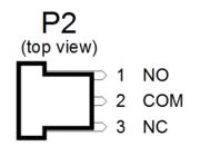
[edit] Pinout
[edit] Mating connector
These connectors (or equivalents) will mate to the board's three-pin Watchdog Reset Out header (P2):
- Molex 22-01-2037 (ramp only)
- Molex 22-01-3037 (ramp + alignment ribs)
[edit] Turning off the relay
After the watchdog timer has activated the on-board Reset Out relay, the application program can deactivate the relay by calling S826_WatchdogEnableWrite() with enable=0, as shown below:
S826_WatchdogEnableWrite(0, 0); // Turn off relay on board0.
[edit] Default safemode states
- In safemode, will all outputs default to power-on/reset conditions if safemode data registers have not been programmed?
Yes, because upon power-up or reset, all safemode data registers are initialized to match their runmode counterparts: DIO outputs are initialized to '0' (i.e., outputs will be pulled up to +5V) and analog outputs are initialized to 0V using the 0 to +5V output range.
[edit] Programming safemode states
It's recommended to program the safemode data registers even if you will be using default values. This will serve to document fail-safe operation in your code and enable you to easily change safemode states if you need to. The following example shows how to do this for board number 0:
// Program fail-safe states for all analog and digital outputs --------------

int aout;                   // analog output channel number
uint SafeDio[] = {0, 0};    // fail-safe DIO states

S826_SafeWrenWrite(0, S826_SAFEN_SWE);                // Write-enable safemode data registers.
S826_DioSafeWrite(0, SafeDio, S826_BITWRITE);         // Program safemode DIO states.
for (aout = 0; aout < S826_NUM_DAC; aout++) {         // Program safemode analog output condition:
  S826_DacRangeWrite(0, aout, S826_DAC_SPAN_0_5, 1);  //   output range
  S826_DacDataWrite(0, aout, 0, 1);                   //   output voltage
}
S826_SafeWrenWrite(0, S826_SAFEN_SWD);                // Protect safemode data registers.

